Every RFP season brings back a word that never really left, just went quiet for a while. “Digital twin” is having another moment, and NVIDIA’s Omniverse partnerships with the likes of Siemens and Rockwell Automation are a big reason why. The demos are genuinely impressive — photorealistic factory floors, robots moving in real time, sensor data streaming into a 3D scene you can walk through in VR. Schaeffler-style deployments get cited in keynotes as proof the industrial metaverse has arrived.
Here’s the uncomfortable truth a lot of plants haven’t fully absorbed: most of what’s being sold and deployed as a “digital twin” today is a visualization layer, not a simulation loop. It looks like the factory. It does not think like the factory. And it almost never talks back to the control system in a way that lets you validate a change before you push it to a PLC. That distinction is the whole ballgame, and it’s worth being precise about it before your plant signs up for another twin initiative.
Three things people call “digital twin” that are not the same product
The term has been stretched to cover at least three fundamentally different capabilities, and vendors are not always eager to clarify which one you’re getting.
The cosmetic twin
This is a 3D or VR representation of the plant, often built from CAD models, sometimes overlaid with live tag data from your SCADA or historian. It’s genuinely useful for training, layout planning, remote walkthroughs, and stakeholder buy-in. It is not a simulation. Nothing computes; it displays. If your “digital twin” project deliverable is a dashboard you can rotate and zoom, you have a visualization tool, and there’s nothing wrong with that as long as you’re not budgeting for it like it’s something more.
The offline simulation model
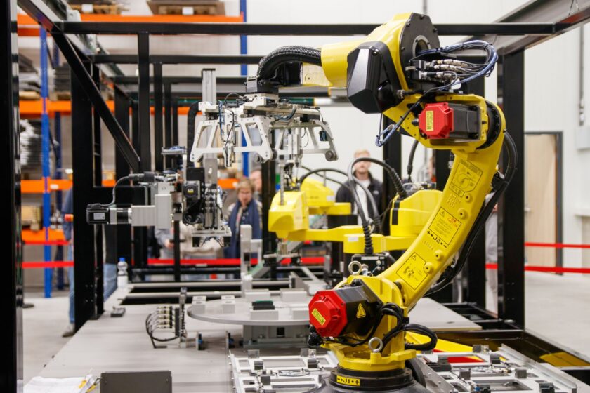
This is real simulation — discrete-event models, physics-based mechanical or thermal models, kinematic robot cells — run in tools like Siemens Plant Simulation, Emulate3D, or a physics engine such as Omniverse’s PhysX-based stack. These models can predict throughput, detect collisions, or validate a robot path. The catch is that they typically run detached from your live control system. You build the model once, validate a design decision, and move on. It’s not synchronized with the plant’s current state, and it doesn’t feed anything back into runtime control automatically.
The closed-loop twin
This is the one everyone implies in a keynote and almost nobody has actually running end to end: a model that stays synchronized with the real asset’s current state, runs simulation continuously or on demand, and produces outputs that can be validated against and pushed into control logic — updated setpoints, revised motion paths, adjusted PLC logic — with a human or automated gate in between. This is simulation-to-control as an actual operational loop, not a slide.
What has to exist before a closed loop is even possible
Closed-loop simulation-to-control isn’t a software feature you buy and switch on. It’s an integration problem, and the plumbing requirements are the part vendors gloss over.
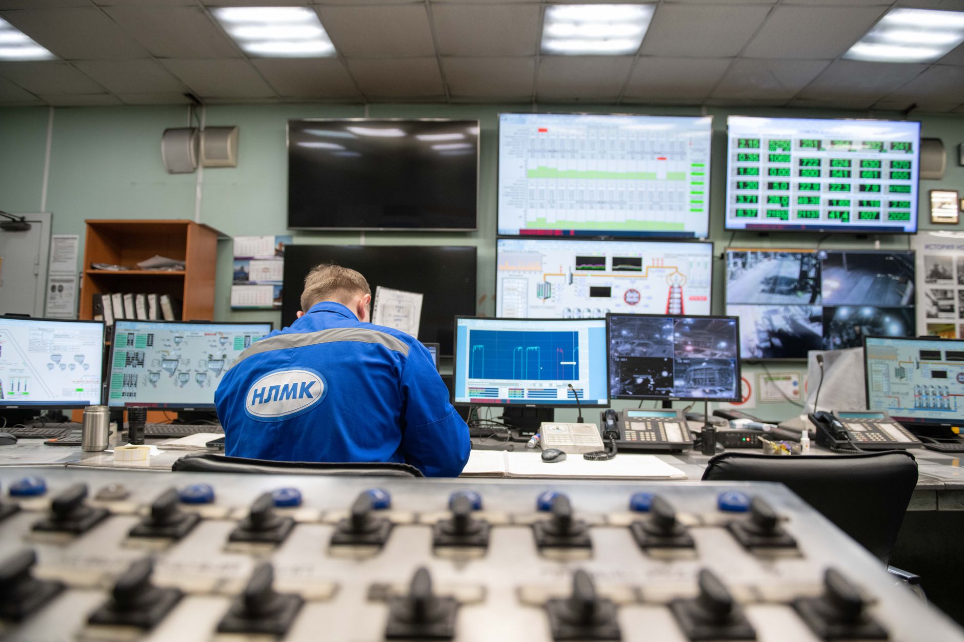
- A live, standardized data path from the floor. OPC UA is the practical baseline here — it gives you a vendor-neutral, semantically structured way to expose PLC and SCADA data to a simulation platform without hand-rolled point mapping for every tag. If your floor communication is still a patchwork of proprietary drivers and one-off OPC DA gateways, you don’t have a foundation for a closed loop; you have a foundation for a nice-looking screen that goes stale the moment something on the floor changes.
- Time-series history with enough fidelity to validate the model against reality. A simulation is only as trustworthy as its calibration. That means a historian or time-series database capturing process variables at a resolution that actually matches your dynamics — not five-minute averages when your cycle time is measured in seconds. Without this, you can’t answer the basic question of whether the model’s predictions track what the plant actually did.
- CAD-to-runtime synchronization that’s maintained, not one-time. The mechanical and electrical “as-designed” model drifts from “as-built” and then from “as-modified” almost immediately after commissioning. If nobody owns the process of updating the twin’s geometry and logic when a fixture gets swapped or a conveyor gets re-routed, the twin becomes a historical artifact within a few months — accurate to the day it was built, wrong ever since.
- A validated interface back into the control layer. This is the piece most deployments simply don’t have. Getting a simulation’s output — a revised path, a new setpoint, a re-sequenced logic block — into a PLC or MES safely requires a defined interface, a review or approval gate, and usually a sandboxed or staged environment to test the change before it touches production. Few plants have built this pipeline, and building it is closer to a controls engineering project than an IT deployment.
A quick framework for sorting fact from RFP filler
When a vendor or an internal team pitches a digital twin initiative, ask three questions before you evaluate anything else about the platform.
- Does the model run continuously against live plant state, or is it a static snapshot refreshed occasionally? If refresh is manual or infrequent, you’re looking at visualization with a data feed, not a synchronized model.
- Can the platform’s simulation output be validated against actual historical outcomes? If nobody can point to a case where the model’s prediction was checked against what the plant actually did, the model hasn’t been proven, no matter how good it looks.
- Is there an actual, documented path from simulation output to a control-system change — with a gate a controls engineer signs off on? If the answer is “we’d export the data and someone would look at it,” that’s not a closed loop. That’s a report.
What’s actually ready now, and what to do about it
The rendering and physics engines behind platforms like Omniverse are legitimately strong, and they’re a real step up from older simulation visualization tools in terms of fidelity and the ability to combine multiple vendors’ equipment models in one scene. Robot cell simulation, layout validation, and collision checking for complex multi-robot work cells are mature enough to trust for design decisions today. That’s not nothing — it can meaningfully shorten commissioning and reduce rework on complex line changes.
What is not mature, industry-wide, is the automated closed loop back into control logic for anything beyond narrow, well-bounded cases like offline PLC logic testing against a simulated cell. Full simulation-to-control loops running continuously in production, adjusting setpoints or sequencing in near-real time based on a synchronized model, remain the exception rather than the rule, and where they exist they tend to be the product of long, bespoke integration work rather than an out-of-box capability.
The practical move for a plant evaluating this now is to stop asking “should we get a digital twin” and start asking which of the three tiers you actually need, and whether your OPC UA coverage, historian fidelity, and change-management process for CAD-to-runtime sync can support anything past the cosmetic layer. If those aren’t in place, that’s the real project — the flashy front end is the easy part, and buying it first just gets you an expensive screen saver with good lighting.
This article was written with the assistance of artificial intelligence. While we aim for accuracy, the information may be incomplete, out of date, or incorrect, and should be independently verified before you rely on it for any decision. It is provided for general information only and does not constitute professional advice.